Saturday, November 04, 2006

DC Motor control with potentiometer

Included a potentiometer to change the speed of the motor...

Here is the code:

int switchPin = 2; // switch input
int motor1Pin = 3; // H-bridge leg 1
int motor2Pin = 4; // H-bridge leg 2
int speedPin = 9; // H-bridge enable pin
int ledPin = 13; //LED

int potPin = 0; //Analogue input from Potentiometer
int potValue = 0; //Value being read from Potentiometer

void setup() {

Serial.begin(9600); //Beggin serial communication

// set the switch as an input:
pinMode(switchPin, INPUT);

// set all the other pins you're using as outputs:
pinMode(motor1Pin, OUTPUT);
pinMode(motor2Pin, OUTPUT);
pinMode(speedPin, OUTPUT);
pinMode(ledPin, OUTPUT);
}

void loop() {

potValue = analogRead(potPin); //Read pot value
Serial.println(potValue); //print value to debugg

// if the switch is high, motor will turn on one direction:
if (digitalRead(switchPin) == HIGH) {
digitalWrite(motor1Pin, LOW); // set leg 1 of the H-bridge low
digitalWrite(motor2Pin, HIGH); // set leg 2 of the H-bridge high
digitalWrite(ledPin, HIGH); //Light up LED for debugging
analogWrite(speedPin, potValue/4); //Write to speed pin to change speed
}
// if the switch is low, motor will turn in the other direction:
else {
digitalWrite(motor1Pin, HIGH); // set leg 1 of the H-bridge high
digitalWrite(motor2Pin, LOW); // set leg 2 of the H-bridge low
analogWrite(speedPin, potValue/4); //Write to speed pin to change speed
blink(ledPin, 3, 100); //Blink LEDs for debugging
}

delay(10); //Delay before next loop
}

/*
blinks an LED
*/
void blink(int whatPin, int howManyTimes, int milliSecs) {
int i = 0;
for ( i = 0; i < howManyTimes; i++) {
digitalWrite(whatPin, HIGH);
delay(milliSecs/2);
digitalWrite(whatPin, LOW);
delay(milliSecs/2);
}
}

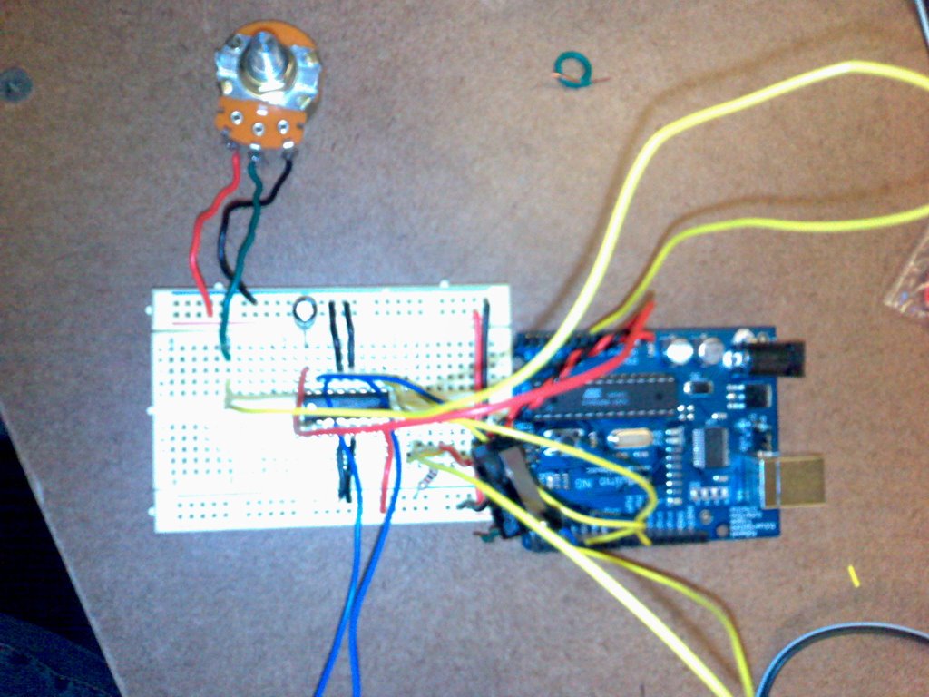
Here is the picture of the circuit:


Here is the video of it working:

LAB - DC Motor Control Using H-bridge

First version of circuit... when switch is pressed, direction of motor rotation is reversed...

Wednesday, November 01, 2006

RUG Video

Arduino Code

//RUG

//PIN Numbers
int okPin = 3;
int buzzPin = 2;
int rugPin = 4;
int readPin = 5;

//PIN variables
int rugValue;

//RFID serial read variables
int val = 0; // variable to store the data from the serial port: 1 = start of byte
int serbyte = 0; // variable to store the VALID data from the port
int length; //length of byte coming through
int status; //serial read data from RFID tag
int data[80]; //data array read from RFID tag
int tagID; //tag to be tracked - set during reset procedure

void setup() {

//Set Pin modes
pinMode(okPin, OUTPUT);
pinMode(buzzPin, OUTPUT);
pinMode(rugPin, INPUT);
pinMode(readPin, OUTPUT);

//Set PIN states
digitalWrite(okPin, LOW);
digitalWrite(buzzPin, LOW);
digitalWrite(readPin, LOW);

Serial.begin(9600); // connect to the serial port

//TEMP
tagID = 55;
}

void loop ()
{
// read the serial port
serbyte = Serial.read();
if (serbyte != -1) {
val = serbyte;
}
else {
val = 0;
}

//If val is 1, its at start of tag reading - read it all to flush
if (val == 1) {
digitalWrite(13, HIGH);
length = Serial.read();
status = Serial.read();
for (int i = 0; i < length - 1; i++){
data[i] = Serial.read();
//Serial.print(data[0]);
//Serial.print(" ");
}
}

//Read RUG switch and serial
rugValue = digitalRead(rugPin); //rugValue = 0 if stepped on
Serial.print(rugValue);

if (rugValue == 1){
if (val == 1){
digitalWrite(buzzPin, LOW);
digitalWrite(okPin, HIGH);
}
else if (val == 0) {
digitalWrite(okPin, LOW);
digitalWrite(buzzPin, HIGH);
}
}
else {
digitalWrite(okPin, LOW);
digitalWrite(buzzPin, LOW);
}


delay(200);

}

RUG Design

Here is a link to the final design we propose and the pictures of our physical model:

Pictures of physical model