Tuesday, September 26, 2006

HW Week 2 DONE!

Ok - got Arduino and my computer to talk correctly...

First part of assignmnet - push button switch lights 2 different lights alternatively:

Green LED on:


Yellow LED on when pressing switch:


Second part of assignment - Lighting Control

Switch 1 toggles between continous or strobe yellow light mode - green light indicates strobe mode (LED ON) and continuous mode (LED OFF). Strobe mode blinks yellow light 8 times.

Here is the video:

Light House project

Light house controller that controls how long light stays ON and OFF.

LEDs indicate if you are increasing or decreasing ON and OFF times.

Brigth LED is the Light House beacon.

Here is the program:

//Light Houes Controller

//Swtiches
int switchONMore = 2; // Increases ON time
int switchONLess = 3; // Decreases ON time
int switchOFFMore = 4; // Increases OFF time
int switchOFFLess = 5; // Decreases OFF time

//LEDs
int LightHouseLed = 6; //Beacon
int OnMoreLed = 7; // ON MORE LED
int OnLessLed = 8; // ON LESS LED
int OffMoreLed = 9; // OFF MORE LED
int OffLessLed = 10; // OFF LED 1

//Variables
int OnTime; //Time light will be ON - 0 to 3 (short to long)
int OffTime; //Time ligth wlll be OFF - 0 to 3 (short to long)
int OnMore; //Increase OnTime
int OnLess; //Decrease OnTime
int OffMore; //Increase OffTime
int OffLess; //Decrease OffTime
int IndLight = 3000; //Indicator light time

void setup() {
//Set Input Pins
pinMode(switchONMore, INPUT); // set the switch pin to be an input
pinMode(switchONLess, INPUT); // set the switch pin to be an input
pinMode(switchOFFMore, INPUT); // set the switch pin to be an input
pinMode(switchOFFLess, INPUT); // set the switch pin to be an input

//Set Output Pins
pinMode(LightHouseLed, OUTPUT); //Lighthouse beacon LED
pinMode(OnMoreLed, OUTPUT); // set LED to be an output
pinMode(OnLessLed, OUTPUT); // set LED to be an output
pinMode(OffMoreLed, OUTPUT); // set LED to be an output
pinMode(OffLessLed, OUTPUT); // set LED to be an output
}

void loop() {
// Read the switch inputs:
OnMore = digitalRead(switchONMore);
OnLess = digitalRead(switchONLess);
OffMore = digitalRead(switchOFFMore);
OffLess = digitalRead(switchOFFLess);

//Increase or decrease timers and indicate on LED
if (OnMore == 1){
OnTime = OnTime + 1;
digitalWrite(OnMoreLed, HIGH); // turn ON indicator
delay(IndLight);
digitalWrite(OnMoreLed, LOW); // turn OFF indicator
}
if (OnLess == 1){
OnTime = OnTime - 1;
digitalWrite(OnLessLed, HIGH); // turn ON indicator
delay(IndLight);
digitalWrite(OnLessLed, LOW); // turn OFF indicator
}
if (OffMore == 1){
OffTime = OffTime + 1;
digitalWrite(OffMoreLed, HIGH); // turn ON indicator
delay(IndLight);
digitalWrite(OffMoreLed, LOW); // turn OFF indicator
}
if (OffLess == 1){
OffTime = OffTime - 1;
digitalWrite(OffLessLed, HIGH); // turn ON indicator
delay(IndLight);
digitalWrite(OffLessLed, LOW); // turn OFF indicator
}

//Blink LightHouse beacon
digitalWrite(LightHouseLed, HIGH); // turn ON beacon
delay(OnTime);
digitalWrite(LightHouseLed, LOW); // turn ON beacon
delay(OffTime);

/*
//STROBE routine
while (switchOnOff == 1 && switchToggle == 1){
//ON and on STROBE
digitalWrite(brightLedPin, HIGH); // turn on LED
delay(3000);
digitalWrite(brightLedPin, LOW); // turn off LED
}

//CONTINUOUS MODE
if (switchOnOff == 1 && switchToggle == 0) {
digitalWrite(brightLedPin, HIGH); // turn on LED
}
else {
digitalWrite(brightLedPin, LOW); // turn off LED
}
*/
}

Now to the wiring!

Sunday, September 24, 2006

HW 2 Attempt

Since I did not get Arduino to work I am posting what I wanted to do with the switch:

Light controller:

Switch 1 toggles from STROBE to CONTINUOUS lighting
Switch 2 turns ligt ON or OFF

Arduino compiled program:

//Light switch

int switchToggle = 5; // Toggles between STROBE or CONTINUOUS
int switchOnOff = 2; // On Off switch
int brightLedPin = 3; // Light source LED
int dimLedPin = 4; // Indicator LED LED INDICATOR => OFF = CONTINUOUS ON = STROBE
int toggleState = 0; // CONTINUOUS = 0 STROBE = 1
int OnOffState = 0; // ON = 1 OFF = 0

void setup() {
pinMode(switchToggle, INPUT); // set the switch pin to be an input
pinMode(switchOnOff, INPUT); // set the switch pin to be an input
pinMode(brightLedPin, OUTPUT); // set the bright LED pin to be an output
pinMode(dimLedPin, OUTPUT); // set the dim LED pin to be an output
}

void loop() {

// Read the switch input:
switchToggle = digitalRead(switchToggle);
switchOnOff = digitalRead(switchOnOff);

//LED INDICATOR OFF = CONTINUOUS, ON = STROBE
if (switchToggle == 0){
digitalWrite(dimLedPin, LOW); // turn off indicator
}
else {
digitalWrite(dimLedPin, HIGH); // turn ion indicator
}

//STROBE routine
while (switchOnOff == 1 && switchToggle == 1){
//ON and on STROBE
digitalWrite(brightLedPin, HIGH); // turn on LED
delay(3000);
digitalWrite(brightLedPin, LOW); // turn off LED
}

//CONTINUOUS MODE
if (switchOnOff == 1 && switchToggle == 0) {
digitalWrite(brightLedPin, HIGH); // turn on LED
}
else {
digitalWrite(brightLedPin, LOW); // turn off LED
}
}

Now have to check to see if I wired the On/Off toggle switch correctly...

Week 1 Class Notes

House Rules
• 10 minutes late – no talking during class

Lesson today – “Enough physics to make a flashlight”

When buying a flashlight you look at:
• Durability
• Light intensity
• What kind of batteries
• How many batteries
• Environmental considerations
• Cost
• Weight
• Cost of upkeep
• Initial investment
• Size
• Rechargeable
• Water proof / floating
• Aesthetics
• Batteries included?
• Brand
• Kind of bulb – durability
• Color of light
• How do direct the light
• All these are design and market niche considerations, unless these were considerations for industrial applications.

What do they all have in common?
• Power source
• Bulb/lamp
• On/off switch

What is different
• Color – appeal / intended audience / preferences / marketing
• Size & shape – how you hold / use it / where – ergonomics
• Texture of material
• Shape of beam
• Brightness
• Physical style of switch – some stay on, some you have to hold to stay on

• Because of these differences you should learn the physical computing side of things.

Terms / jargon on the package we do not recognize:
• LED
• 6V latten battery
• KPR 113 – K13 bulb
• 120V AC
• 2.5 Volts
• 0.3 amps
• 60 Hz
• H14 flashlight bulb
• Krypton bulb
• Polarized
• Adapter
• Watts

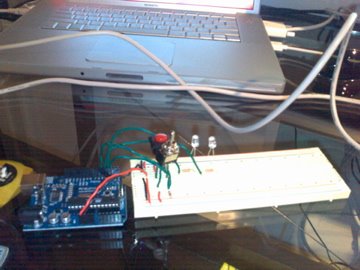
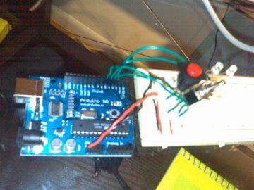
Let’s build a flashlight
• Biking headlight – to see or to be seen
• Headlight to work on pComp project w/o waking up roommates
• Laser pointer
• Purse light

Glasses
• Limiting factor – what should we worry about the most?
• Size and weight
• Color
• Switch style
• Bulb
• LED (Light Emitting Diode)

When shopping for light bulb you look for Power/Watts – which do NOT relate to brightness
• Watts = Power = Volts/second
• www.jameco.com - good for browsing
• Opto & illumination
• Lamps – incandescent

Description is size & shape
• It’s light
• It’s small
• It does not heat up
• Consumes less power
• Brightness / Luminous intensity
• MSCP (Mean Spherical Candle Power)
• MCD (Milli candela)

Watts
• Ability to do work
• Energy/time
• E = mc2
• E = force x distance
• Mass ≠ weight
• Weight depends on gravity
• Mass is resistance to change
• m = E / c2
• Coulomb/ second
• Current = amperage = amps = a
• Voltage is like potential / pressure / gravitational pull

Amperage
• How many electrons

Voltage
• How much strength they have

Watts = Volts x Amps

Atoms
• Electrons – valence sheet gardens

Electricity
• Electrons go from one atom to the other
• Atoms with “vacancies” are good conductress
• Insulators have no/little vacancies
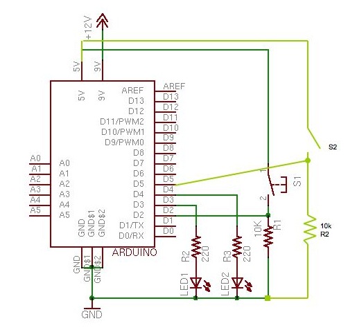
Circuit

• All LEDs have a flat side – flat goes to 0V (ground)

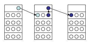
Bread board (protyping board)
• Put LEDs across different rows
• Voltage regulator
• Takes the voltage down to appropriate value
• Instead of using batteries, plug into wall
• 2 LEDs of 1.7V = 3.4 voltage regulator
• Most microchips use 5 Volts
• IGO – In Ground Out
• Red Line => Voltage

Strip wire 1/4 or 1/8 of inch
• Place on bead board where you want it
• Take out
• Cut / strip / back in
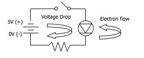
In diagram:
Voltage is 5V, LED is 1,7 - need resistor not to blow it up - what resistance?
-> 5.0 V (power supply) - 1.7 V (LED) = 3.3 V (need to drop ot this current)
-> V = IR => R = V / I => R = 5v / 0.02 a => R = 165 Ω
-> 165Ω would be exact - always put a greater resistance than required - 220Ω would do

• Ohm’s Law => V = IR (Voltage = Current x Resistance (ohms Ω))
• W = IV (Watts = Current x Voltage)

Resitors Color code
• 0 = black
• 1 = brown
• 2 = red
• Poster in the lab
• Nice link:
• http://www.breakup.de/resources/resistor.html

Switches
• All kinds – basically good marketing on two metal pieces touching each other
• ON – closed circuit
• OFF – open circuit

ADMIN STUFF
• We are a week off the other classes
• Friday help sessions are a week ahead
• “Make up” session on the 23rd?
• Read syllabus
• Choose week you do notes on
• Join pComp list serve
• Introduce yourself on the class site
• Sign up for shop cleaning
• Do shop safety
• Look at links
• Think about the light bulb glasses
• Keep journal for class – document your work
• Look for blog with RSS feed – it will feed the wiki
• Read chapters 1 – 3 of Physical Computing book
• Course packet – buy it at NYU book store

Assignment 2 - part 1

Using Arduino - microcontroller... had some hick-ups installing it but finally got it to be recognized via the USB port and have it get the program... but now the circuit does not work... will have to get some help tomorrow morning...


Sunday, September 17, 2006

Assignment 1 - part 5

Potentiometer - home made dimmer:

Assignment 1 - part 4

Three LEDs in parallel lit up nice and strong:

Assignment 1 - part 3

Three LEDs in series - did not light up - not enough voltage:

Assignment 1 - part 2

2. Two LEDs in series - light up dimly - no need for resistance since each LED will drop the voltage

Saturday, September 16, 2006

Assignment 1 - part 1

Switch lit up LED - yeay!